


Reactive power is one of the most complex concepts in electricity, and one which is rarely explained in clear terms, however it is an essential facet of power systems, so it is worth taking a moment to understand what it is. To do this it is useful to re-cap some basic physics.
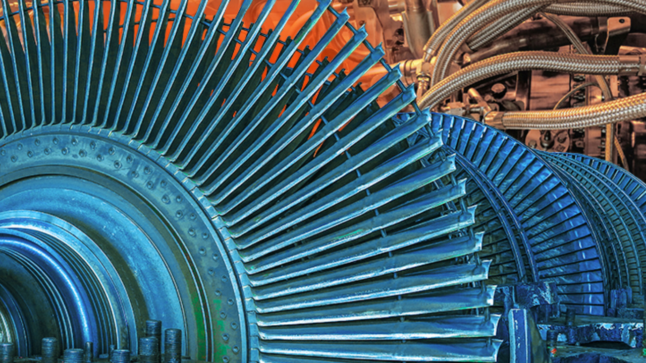
Alternating currents arise from the rotation of a magnet inside another magnetic field. In a steam-driven generator, high pressure steam turns a turbine, which turns a rotor (also known as an armature) mounted inside a stator. A generator running at 3,000 revolutions per minute, with two magnetic poles, produces electricity at a frequency of 50 Hz.
In a circuit containing only resistance, the current and voltage waveforms are in phase ie they reach their maxima and minima at the same times. However, in circuits containing capacitance and inductance, the maxima and minima of the current and voltage occur at different times: they are out of phase. In a purely inductive circuit, current lags voltage by 90o, whereas in a purely capacitive circuit it leads voltage by 90o.
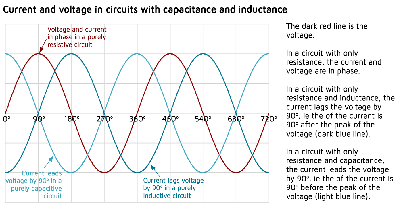
This is because energy is stored in capacitors and inductors whereas it is consumed in resistors.
Capacitors store energy in their electric fields because they charge and discharge in an attempt to keep voltage constant: they energy is stored when the capacitor is charging and returned to the source when it discharges. This action causes the current waveform to lead the voltage waveform.
Inductors store energy in their magnetic fields because they expand and collapse their magnetic fields in an attempt to keep current constant: the energy is stored in the magnetic field when the field is expanding and returned to the source when the field collapses.
Reactive power is a function of a system’s amperage, and it is not consumed in the circuit, it is all returned to the source, which is why reactive power is often described as energy that moves back and forth within a circuit. In this sense it is not “active” or “real” since it is not used to carry out work such as powering a light.
True (active) power is consumed, with none of it returning to the source. As alternating current is constantly changing, the cycle of expansion and collapse of the magnetic and electrostatic fields is constantly taking place within a circuit containing inductive and capacitive elements. A more detailed explanation including an overview of the relevant maths can be found here.
Devices which store energy by virtue of a magnetic field produced by a flow of current (ie inductors) are said to absorb reactive power; those which store energy by virtue of electric fields (ie capacitors) are said to generate reactive power.
Why is reactive power important in electricity grids?
While the rotation of synchronous turbines creates electricity whose current and voltage varies at a certain frequency, this frequency will change if the active power demand on the generator is more or less than the active power which the generator is supplying.
If demand exceeds supply, the current drawn increases, causing the voltage to fall (from Ohm’s Law), which can lead generators to trip, motors to overheat and other equipment failures. If the active power demand falls below the generator’s active power output, then voltage rises, which damages the insulation of windings and can cause dangerous electrical discharges.
Similarly, when reactive power generation is greater than reactive power absorption, the voltage increases, and vice versa. The ability of reactive power to move around the grid is limited by line losses to a greater extent than for active power, meaning that reactive power must be balanced on a regional basis (unlike active power, where generation in one region can be used to meet demand and provide voltage support in another region. Reactive power can vary vey significantly between regions of the same power grid, as is the case in GB.
Generators typically have limited controllable variability in their active power output – in order to manage changes in demand, electricity system operators need to instruct different generators to start up or shut down in response to changes in demand. But these step changes in generation are not well aligned with changes in demand which tend to be more incremental. This means that other techniques are necessary to maintain a stable voltage.
In addition to different types of generators with different outputs and ramping characteristics, system operators make use of the inherent properties of inductors and capacitors to manage the rate of change of voltage.
Sources of reactive power include synchronous generators and synchronous condensers, power electronic devices, and shunt capacitors and inductors.
Power lines also produce reactive power since the current flowing through the wires produces a net magnetic flux – a lightly loaded line acts as a source of reactive power generator while heavily loaded line acts as an absorber of reactive power.
Other absorbers of reactive power are inductive motors, transformers, and under-excited synchronous machines.
Power factors and the power triangle
In ac circuits, current and voltage are normally out of phase due to the presence of a wide range of different types of components. As a result, not all the power produced by a generator can be used to carry out work since some of it is stored in the inductive and capacitive elements.
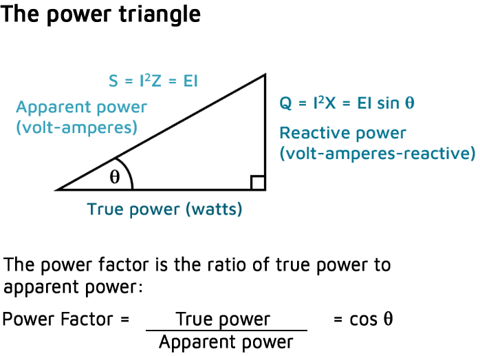
The power triangle, shown in the diagram, equates ac power to dc power by showing the relationship between generator output (apparent power – S) in volt-amperes (VA), usable power (true power – P) in watts, and wasted or stored power (reactive power – Q) in volt-amperes-reactive (VAR). The phase angle (q) represents the inefficiency of the ac circuit and corresponds to the total reactive impedance (Z) to the current flow in the circuit.
The power factor represents the efficiency level of generated power to usable power, which is shown in the power triangle.
Apparent power is the power delivered to an electrical circuit:
S = I2Z = ITE
S is the apparent power in volt-amperes
I is the dc equivalent current in amperes (RMS value)
E is the dc equivalent voltage (in volts) (RMS value)
Z is the impedance in ohms (W)
True power (P) is the power consumed by resistive loads on the circuit:
P = I2R = EI cos θ
R is the resistance in ohms (W)
θ is the angle between the current and voltage sine waves
Reactive power (Q) consumed (stored) in an ac circuit because of the expansion and collapse of magnetic (inductive) and electrostatic (capacitive) fields:
Q = I2X = EI sin θ
X is the net reactance in ohms (W)
Impact of the energy transition on voltage management
There are three main ways in which the de-carbonisation of the electricity system is affecting voltage management: in addition to the traditional variability of demand, a large proportion of supply is now variable due to the intermittency of renewable generation such as wind and solar power. This makes balancing supply and demand in real time more challenging.
At the same time, there is a growing amount of generation connected at the distribution level. This behaves like demand on the transmission system, and has the effect of increasing voltage levels, particularly in the summer due to the combined effects of reduced seasonal demand with higher solar pv output. This is creating an increased requirement to absorb reactive power in order to prevent voltage reaching excessive levels.
Finally, traditional sources and sinks of reactive power, conventional synchronous generators, are increasingly being displaced by intermittent renewable generation. As a result they require compensation if they are to synchronise for the provision of reactive power alone rather than with active power as was historically the case. This is driving a need for new types of market that incentivise the provision of reactive power, de-coupling the procurement of reactive and active power, with providers operating at a power factor of zero or close to zero.
“The conversion of an aging traditional fossil fuelled power plant to provide grid stability services is what the energy transition is all about. It is so satisfying to see the same assets reused in a way that enables the transition and can be considered recycling in its purest form,”
– Mick Farr, Chief Executive Officer at Triton Power
Synchronous generators and synchronous condensers can either generate or absorb reactive power based on their level of excitation. A normal level of excitation occurs when the current which creates the magnetic field of the stator is such that the output current and voltage of the generator are in phase (this gives a power factor of 1). If the input current is lower than this level, the output current will lag the voltage (giving a power factor below 1) and the generator will be “under-excited” and act as an absorber of reactive power. Conversely, if the input current is above this level, then the output current leads the voltage (and the power factor is greater than 1), and the generator will produce reactive power.
This flexibility makes synchronous machines a useful tool in managing reactive power. The addition of a clutch can allow a generator to switch active power generation on or off while still allowing reactive power to be generated or absorbed by the machine. Similar modifications can be made to reciprocating engines – a clutch can completely disengage the prime mover from the generator when only reactive power is needed, automatically re-engaging when active power is needed.
In 2021, National Grid Electricity System Operator (NG ESO), the system operator in Great Britain, entered into a new six-year partnership with Triton Power’s Deeside Power Station, for the provision of reactive power and inertia grid support services.
The plant, a combined cycle gas turbine power plant in Flintshire originally consisted of two Alstom 13E2 gas turbines, two CMI Heat Recovery Steam Generators HRSG and an Alstom steam turbine, and had been shut down and in preservation since March 2018. Under the terms of the stability contract, awarded in January 2020, the two gas turbines will provide the grid with support services while the steam generators and turbine will remain in preservation. This is achieved through using a small amount of power from the grid to spin the rotors and provide stability.


